Topic 2: System simulation example
Abschnittsübersicht
-
-
Teilnehmer/innen müssenAls erledigt kennzeichnen
System simulation example
This example will give a short overview on how to build a simulation focussing on thermal-energetic performance. It shows the procedure from understanding a hydraulic scheme to finally developing a simulation deck and following performing of simulations.
In figure 1, you can find the hydraulic scheme of the HyCool project, following the public “Deliverable 5.1 Drawing of the hydraulic schematic”. This scheme shows the interconnection of the individual elements within the solar cooling system. On the upper left corner, you find the display of the Fresnel Solar collector field. At the bottom of the schematic, you can find the display of the hybrid chiller composition, being connected to a cooler (left), a hot water tank (above) and the connection to the chilled water circuit. Within this hydraulic scheme, the desired flow rates, given in m3/hr, and temperatures of the heat transfer medium, given in °C, are described.
This hydraulic scheme will be integrated into the simulation software TRNSYS.
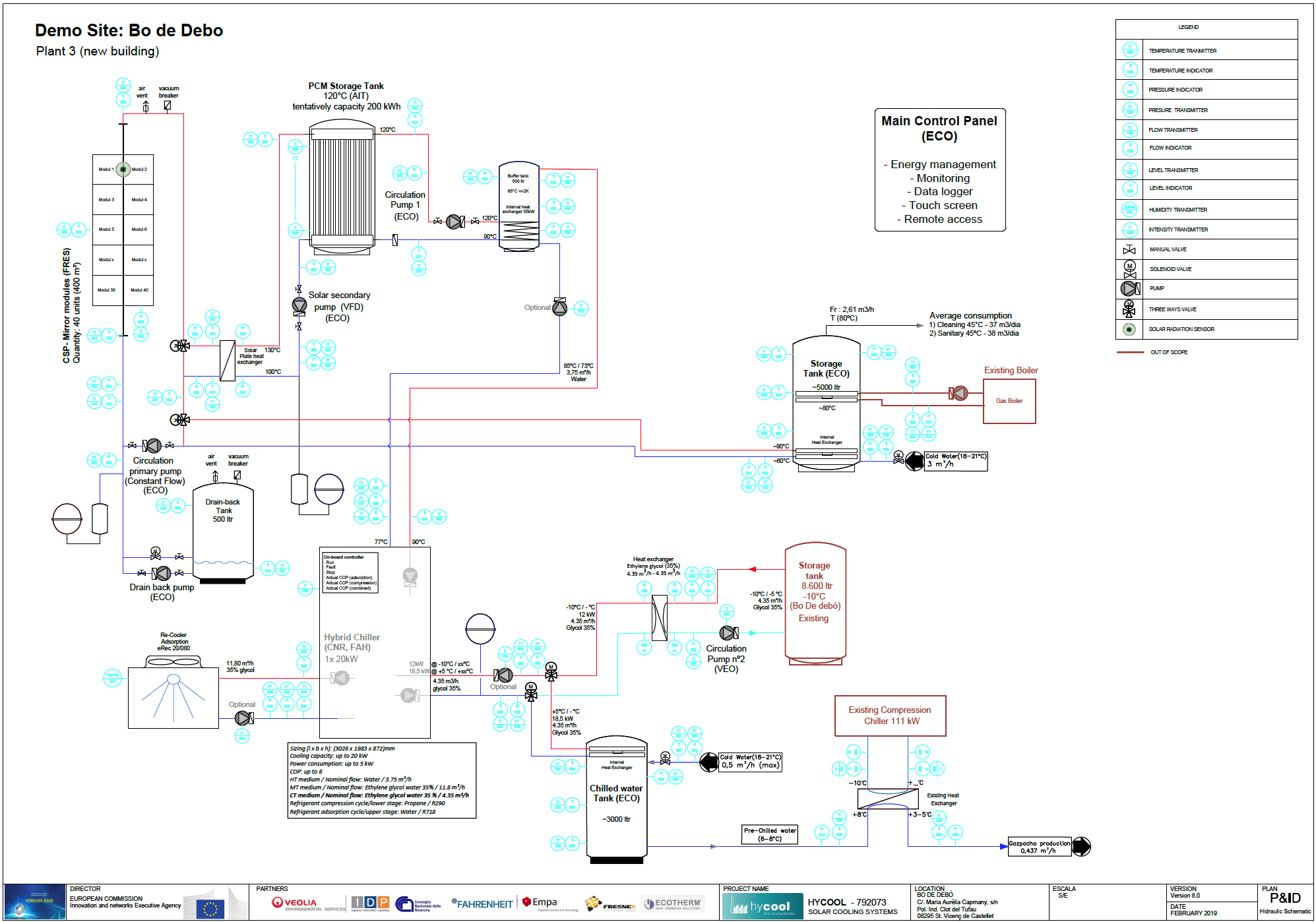
Figure 1: Hydraulic scheme of a HyCool solar cooling plant. (Source: HyCool project, Deliverable 5.1)The scheme below covers the previously described system in a simplified way. It shows the basic principle of the solar cooling system.
The principle is running by following steps:
- Distribution of heat from the solar collector plant primarily to the PCM storage. Once the PCM storage is full, further heat will be distributed to another storage for heating purpose (step 5).
- Distribution of heat from the PCM storage at high level (90- 140 °C) to the buffer tank at a lower heat level (70 – 100 °C).
- Distribution of heat from the buffer tank to the Hybrid Chiller. Heat is distributed at a level of 70 – 90 °C.
- Distribution of cold to the user.
- Distribution of heat to the user.
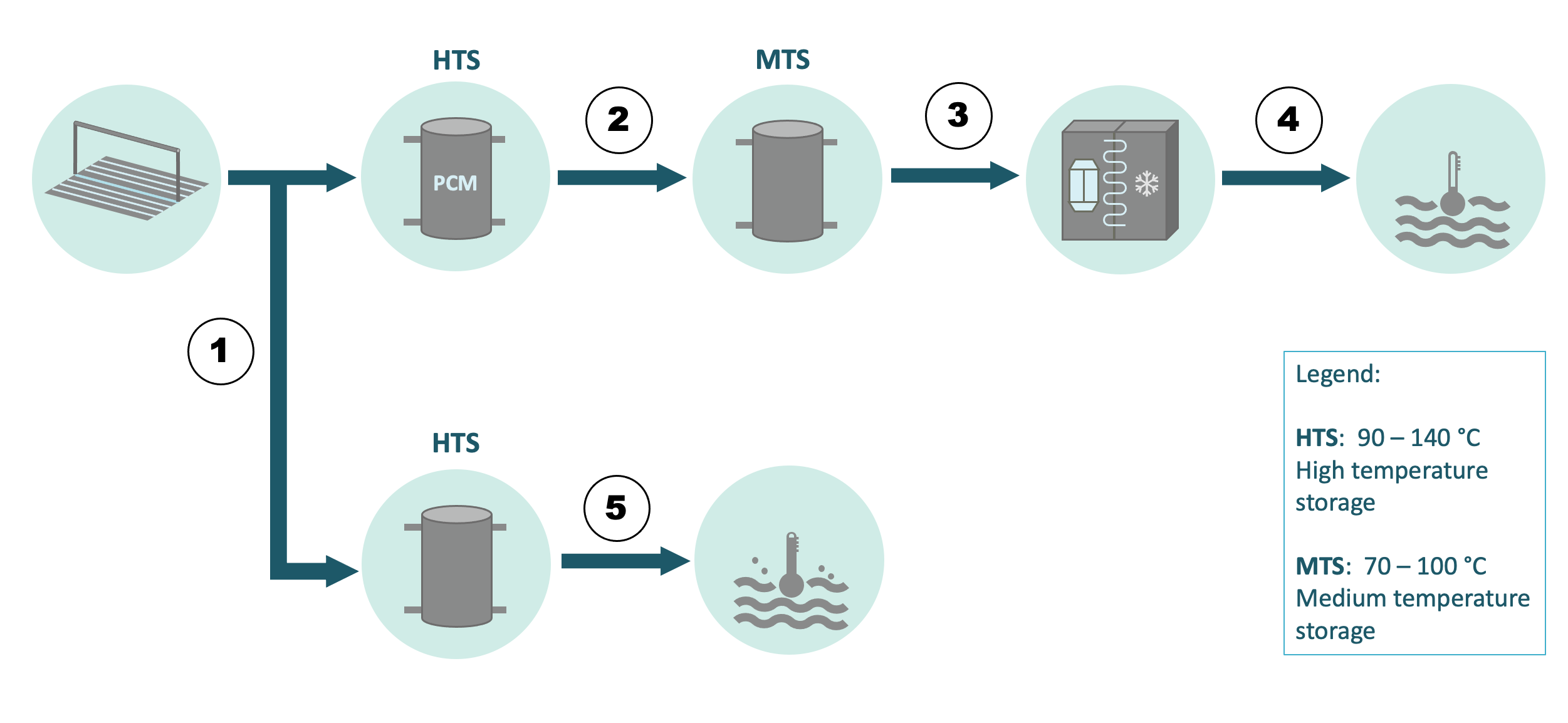
Figure 2: Simplified principle of the solar cooling plant. (Source: JER)Figure 3 shows the display of the solar cooling system within the simulation deck of TRNSYS simulation software.
TRNSYS simulation software models each component individually. The user is able to connect the single components with bonds, transferring information, such as flowrate, temperature or more simple signals such as “ON” or “OFF”.
The previous figure 2, showing the basic principle of the HyCool system for a plant, describes the system overall in 5 steps. In figure 3, these steps are given in the simulation deck for a better understanding. The goal of this simulation is the examination on the thermal energetic performance of the system throughout the course of a year.
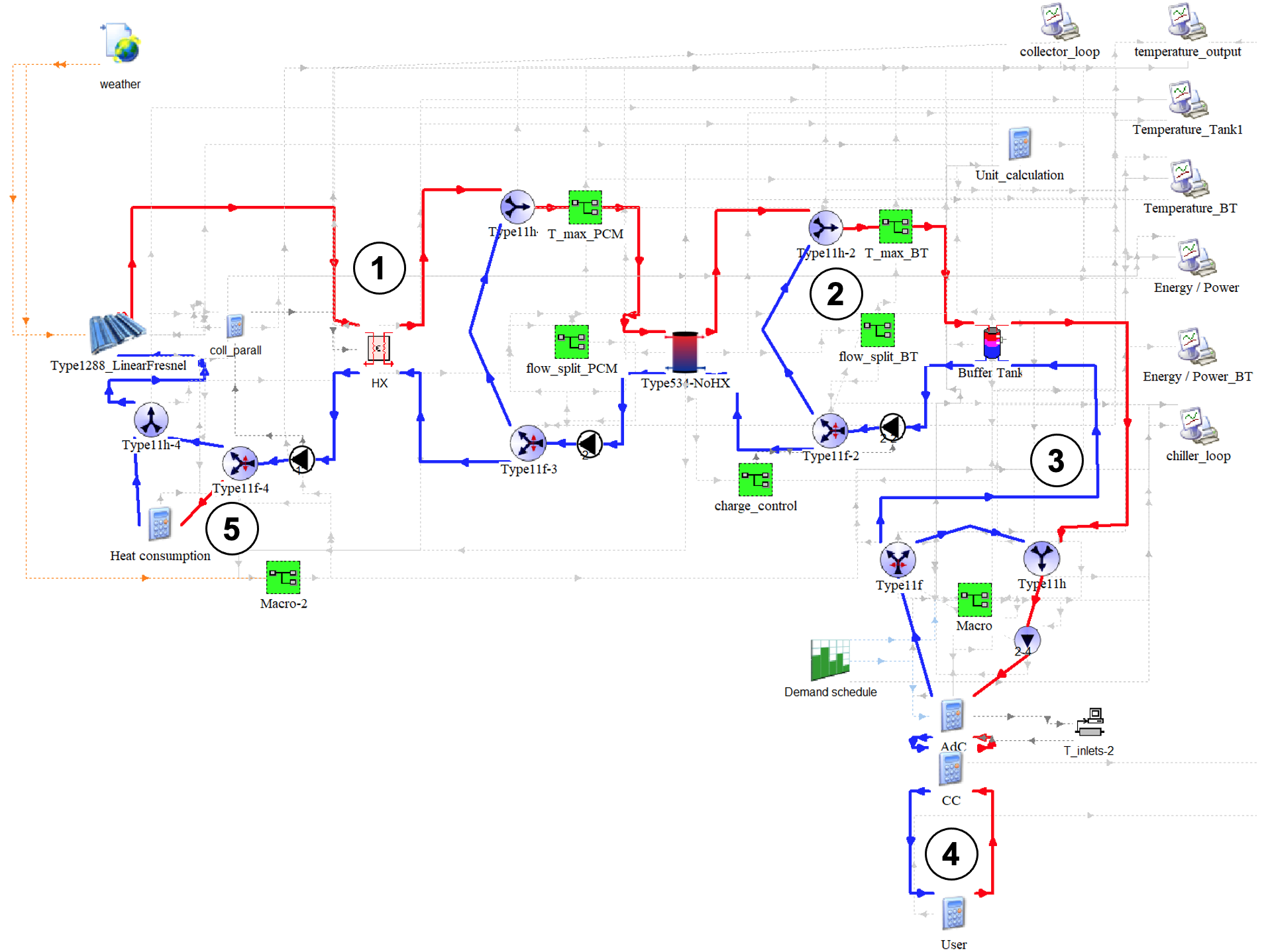
Figure 3: Overview of the TRNSYS simulation deck, representing the HyCool solar cooling plant. (Source: JER)
- Distribution of heat from the solar collector plant primarily to the PCM storage. Once the PCM storage is full, further heat will be distributed to another storage for heating purpose (step 5).
-